Views: 0 Author: Site Editor Publish Time: 2026-08-12 Origin: Site
Capital expenditure decisions often shape factory floors for decades. Choosing the right tooling setup dictates daily operational expenses, achievable cycle times, and overall equipment effectiveness (OEE). Many plant managers fall for a common industry myth. They assume adding more cavities automatically creates higher profitability. This assumption frequently backfires on the production floor. Over-specifying your tooling wastes valuable capital and creates severe machinery mismatches. Conversely, under-specifying creates immediate bottlenecks across your production lines.
We designed this guide to provide a concrete, engineering-backed evaluation framework. Procurement leaders and plant managers need practical guidelines. You must match cavity configurations to actual production realities. You will learn how to calculate precise volume requirements. We will show you how to verify machine compatibility and navigate complex cooling constraints. By the end of this analysis, you can confidently determine the optimal configuration for your specific manufacturing floor.
Your ideal PET preform mold cavity count must align mathematically with your annual production volume targets and allowable cycle times.
Selecting a high-cavity mold requires rigorous verification of existing injection molding machine specs, including clamping force, shot weight, and tie-bar spacing.
Mold complexity increases non-linearly with cavity count; evaluate the long-term maintenance resources and cooling system requirements before scaling up.
Specific applications—like an edible oil preform mold or a high-cavity jar bottle preform mold—require unique pitch and runner balancing considerations that dictate cavity limits.
To hit aggressive production targets, you must calculate exact volume requirements first. Choosing the right PET preform mold cavity count requires rigorous math. We cannot rely on guesswork or generic industry averages. Production planners must map annual bottle demand directly to their tooling requirements. You should utilize a standard volume-to-cavity formula. Calculate your minimum requirements by dividing your annual demand by your total production hours, adjusted for cycle times.
The standard formula looks like this: Annual Demand / [Working Days × Shifts × Hours × (3600 / Cycle Time)]. This calculation reveals the theoretical baseline. However, theoretical calculations rarely survive contact with reality. Cycle time fluctuates dramatically based on preform wall thickness and overall gram weight. Heavy preforms require extended cooling inside the tool. They also demand more recovery time from the injection molding machine. You must factor these delays into your baseline calculations.
Consider the realities of thermal management. A massive 72-cavity mold might run slowly due to poor cooling channel efficiency. In many cases, a highly optimized 48-cavity mold yields higher daily output. Fast, stable cycles often beat slow, high-cavity cycles. Scalability must balance against actual utilization rates. You lose money running a massive mold at 50% capacity. We recommend sizing the tooling for 80-85% sustained OEE. Focus on reliable, continuous output rather than chasing theoretical maximums.
Cycle Time and Output Correlation Chart
Cavity Configuration | Cycle Time (Seconds) | Hourly Output (Units) | Estimated OEE Impact |
|---|---|---|---|
32 Cavities | 12.0 | 9,600 | High Stability (90%+) |
48 Cavities | 14.5 | 11,917 | Optimal Balance (85%+) |
72 Cavities | 18.0 | 14,400 | Cooling Constrained (75%+) |
Before finalizing any purchase, plant managers must verify their existing hardware. A high-capacity mold offers zero value if it exceeds your machine capabilities. Tonnage and shot weight serve as your primary constraints. You must match the cavity count to the clamping force of your injection molding machine. Engineers calculate required tonnage based on the projected area of all cavities combined. Furthermore, the machine barrel must handle the maximum plasticizing capacity. Exceeding this capacity causes incomplete filling or severe resin degradation.
Physical space requirements often derail upgrade projects. Your tooling must physically fit within the machine envelope. You must verify two critical dimensions before proceeding. First, measure the tie-bar spacing. The mold base must slide smoothly between the machine tie bars during installation. Second, calculate the daylight and opening stroke. You need sufficient clearance for robot arms or free-drop ejection mechanisms. Longer preforms demand significantly greater opening strokes to eject cleanly without scratching.
Facility infrastructure limits present another common hurdle. Scaling up requires highly robust auxiliary equipment. You cannot simply attach a massive tool to an undersized chiller. Higher outputs generate massive thermal loads.
Chiller Capacity: Ensure your cooling towers and chillers can extract heat fast enough to maintain cycle times.
Air Compressors: High-speed ejection and valve gate operations require stable, high-pressure air lines.
Material Dryers: Increased resin consumption demands larger desiccant dryers to prevent moisture-related defects.
Crane Clearance: Verify your overhead cranes possess the tonnage rating and vertical clearance to safely maneuver massive steel mold bases.
Not all preforms share the same dimensional constraints. Standard beverage applications scale easily. Common 28mm or 30mm water bottle preforms feature thin walls and light gram weights. You can often push these designs to 96 or 144 cavities. The compact neck sizes allow engineers to tightly pack the cavities. This tight layout maximizes the steel surface area on standard machine platens.
However, heavier designs introduce severe spatial and thermal limitations. Consider an edible oil preform mold. Edible oil containers use heavy gram weights to support large liquid volumes. They feature notably thick walls. These dimensions demand extended cooling times to prevent deformation upon ejection. They also require larger pitch dimensions. The pitch represents the center-to-center distance between adjacent cavities. A larger pitch naturally caps the feasible total count you can physically arrange.
Similarly, a high-cavity jar bottle preform mold faces strict geometric limits. Wide-mouth jar preforms require significantly larger neck rings. The expansive center-to-center distances restrict the total cavities fitting on your machine. You simply run out of available steel space. Forcing too many large cavities into a standard mold base compromises structural integrity. It leaves inadequate room for robust cooling channels, ultimately sabotaging product quality.
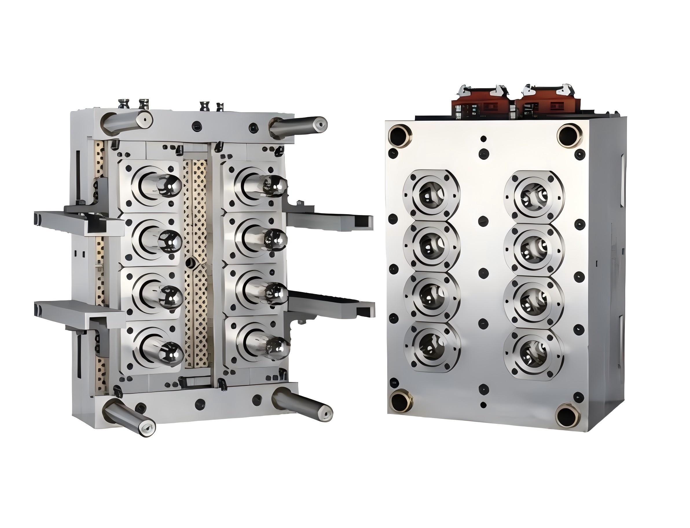
Scaling up introduces non-linear complexity. A massive PET preform mold challenges both quality control and maintenance teams. Hot runner balancing represents the highest technical hurdle. Achieving perfect thermal and flow balance gets exponentially harder past 48 cavities. Unbalanced polymer flow causes severe defects across the grid. You risk weight variations between the inner and outer cavities. You may also encounter short shots. Furthermore, unbalanced flow creates localized shear heat, which generates dangerous levels of acetaldehyde (AA) in beverage containers.
Cooling system efficacy directly dictates preform quality. As you increase cavities, you must weave complex water channel routing through tight steel spaces. Poorly routed channels cause uneven cooling across the layout. Uneven cooling elevates the risk of preform crystallinity. This defect manifests as an unacceptable milky haze on the final bottle. Proper turbulent flow requires high water pressure. You must ensure your facility pumps can overcome the massive pressure drops inside a complex tool.
Do not underestimate maintenance overhead. Doubling your cavities directly doubles your wear parts. You must maintain twice as many core pins, neck rings, and nozzle tips. Assess your in-house maintenance capabilities honestly. Do you have skilled technicians available? Do you stock adequate spare parts? Minimizing downtime requires aggressive preventative maintenance. A single damaged cavity in a massive tool can shut down your entire production line if you lack shut-off valve capabilities.
Evaluating the ultimate preform mold cavity count requires comparing immediate returns and long-term downtime risks. You must evaluate the operational cost comparison carefully. Model a comparison between buying one 72-cavity system versus two 36-cavity tools. Dual systems require higher upfront capital and two injection molding machines. However, they offer invaluable built-in redundancy. If one system requires emergency maintenance, your production continues at half capacity. A single massive tool maximizes floor space but completely halts output during repairs.
Smart buyers employ strict risk mitigation strategies. Never max out your existing machine capacity. We highly recommend leaving a 10-15% safety margin on injection pressure and clamping force. Running machinery at 100% capacity accelerates wear on hydraulic seals and tie bars. A safety margin absorbs natural viscosity variations in recycled PET (rPET) materials. It also guarantees stable clamp lock-up, preventing flash defects.
Procurement teams should follow clear next-step actions before issuing purchase orders. Protect your investment by executing these specific buyer protocols:
Request detailed mold layouts from your makers. Insist on a written cycle time guarantee based on your specific resin grade.
Require a formal compatibility sign-off. Ensure both the mold maker and the injection molding machine OEM approve the integration.
Audit the vendor’s after-sales support network. Verify their lead times for replacement core pins and hot runner nozzles.
Evaluate the cooling channel flow rates. Demand simulation reports proving turbulent water flow reaches every cavity.
Capacity Matching Safety Matrix
Machine Spec | Required Tool Spec | Recommended Safety Margin |
|---|---|---|
Maximum Clamping Force | Total Projected Area Force | Maintain 15% Buffer |
Max Shot Weight (PET) | Total Resin + Sprue Weight | Maintain 20% Buffer |
Distance Between Tie Bars | Mold Base Width/Height | Minimum 50mm Clearance |
The optimal tooling setup represents a careful balance. You must weigh aggressive production goals against conservative engineering constraints. Do not let theoretical spreadsheets dictate factory floor realities. Prioritizing tool reliability, cooling efficiency, and strict machine compatibility always yields better results. This practical approach generates a faster return on investment than simply purchasing the largest tool available on the market.
Align your capacity carefully with actual order volumes and maintenance capabilities. Evaluate spatial constraints early, especially for specialized thick-wall or wide-mouth applications. We highly recommend consulting an experienced tooling engineer before finalizing your specifications. Request a custom output-to-machine-matching analysis to validate your mathematical models. Making informed, data-driven decisions protects your capital and ensures decades of profitable manufacturing.
A: Buying two 24-cavity molds offers valuable production redundancy. If one tool requires maintenance, your line continues operating at half capacity. However, dual molds require higher upfront tooling costs and two injection molding machines. A single 48-cavity tool maximizes output per square foot but halts all production during repairs. Choose based on your facility space and risk tolerance.
A: Thick preform walls demand extended cooling times inside the tool. They also require higher injection pressures and more plasticizing capacity from the machine barrel. These factors slow down cycle times. The intense cooling requirements limit how densely cavities can be packed into the steel base, effectively restricting the maximum count.
A: Yes, you can physically run a smaller mold on a larger machine. However, we strongly caution against this practice. It creates highly inefficient machine utilization. The oversized barrel may degrade the PET resin due to extended residence times. It also generates excessive and wasteful energy costs per part produced.
A: Industry standards typically follow specific even-numbered increments based on balanced hot runner layouts. The most common configurations include 16, 24, 32, 48, 72, 96, 128, and 144 cavities. These symmetrical layouts ensure equal flow distances from the central sprue to every individual cavity, maintaining consistent part quality.