Views: 0 Author: Site Editor Publish Time: 2026-06-26 Origin: Site
Tooling investments carry incredibly high stakes for manufacturing operations everywhere. A sudden mold failure or suboptimal cycle times directly erode manufacturing margins. These physical assets form the reliable heartbeat of continuous production lines. Navigating material trade-offs requires deep technical knowledge and extensive practical experience. Engineering teams must align design-for-manufacturability realities alongside vendor capabilities seamlessly. Poor initial choices inevitably lead to production delays and wasted capital. Getting the engineering foundation right is absolutely essential before cutting any steel. This guide provides a clear, data-oriented framework to minimize long-term piece-part costs and accelerate time-to-market. You will learn how to evaluate baseline production requirements accurately. We will explore how to select ideal metal alloys and optimize tool geometry for maximum yield. Expect actionable insights to refine your entire tooling strategy.
Tooling material dictates production volume limits: Aluminum suits bridge tooling, while hardened steel (H13/P20) is required for high-volume runs.
Thermal management and cooling channel design are the primary drivers of cycle time reduction.
Prefabricated mold bases combined with custom cavity inserts offer a proven method to reduce upfront lead times by 20-30%.
Selecting a reliable industrial mold manufacturer requires vetting their in-house DfM expertise, maintenance SLAs, and quality control certifications.
We must define baseline operational requirements clearly before comparing metals. Skipping this step leads to mismatched performance expectations. The initial scoping phase dictates the entire project trajectory.
First, establish your absolute production volume. Industry standards categorize tooling into distinct performance classes. Class 105 and 104 represent low-volume or rapid prototype runs. Bridge tooling typically falls into this specific category. Conversely, Class 101 and 102 define high-volume mass production. These robust molds must endure millions of cycles without failing mechanically. High-volume targets demand extremely resilient materials. You cannot use soft alloys for Class 101 applications. The tool will simply degrade too quickly under immense clamping pressures.
Next, assess your chosen resin carefully. Different polymers interact with metal surfaces differently during injection. Evaluate how abrasive or corrosive the plastic is. Glass-filled polymers act as severe abrasive agents. They scrape against cavity walls aggressively during every single injection cycle. This continuous friction requires highly wear-resistant tooling. Corrosive materials like PVC demand specialized stainless steel options. Neglecting resin characteristics guarantees premature tool wear.
Cycle time directly impacts your manufacturing profitability. Establish the baseline acceptable cooling rate early in the design phase. Cooling usually consumes the largest portion of the injection cycle. This specific objective dictates thermal conductivity requirements. Faster cooling demands materials that transfer heat rapidly away from the part. You must balance this thermal need against mechanical wear resistance.
Evaluate your core tooling architecture strategy. Standard frames often present a smarter, more economical choice. Compare the viability of using standard frames to house custom cavities. Using a prefabricated mold base reduces lead times significantly. It lowers your initial capital expenditure drastically. Custom cavity blocks fit neatly inside these standard bases. You save weeks of heavy machining time on the exterior frame.
Material selection dictates production longevity and daily efficiency. Engineers must balance hardness, thermal conductivity, and machinability carefully to achieve optimal results.
Hardened tool steels dominate high-volume manufacturing environments. Alloys like H13 and S136 handle abrasive resins beautifully. They offer exceptional long-term durability and structural rigidity. These metals polish to a high optical mirror finish easily. However, they carry notable trade-offs. They demand higher upfront machining effort and specialized tooling. Lead times stretch longer due to complex vacuum heat treatments. Additionally, they exhibit lower thermal conductivity than softer metals.
Pre-hardened steels present a highly balanced approach for manufacturers. P20 stands as the undisputed industry workhorse. It suits medium-volume production perfectly. It balances machining costs and durability exceptionally well. You will often see P20 in standard plastic injection mold applications globally. It also serves as an excellent choice for large-scale preform mold bases. It machines faster than H13 and requires no post-machining heat treatment.
Aluminum alloys excel at rapid prototyping tasks. High-grade options like 7075-T6 handle low-volume runs effortlessly. They offer vastly superior heat dissipation compared to steel. This accelerates cycle times dramatically. Unfortunately, aluminum suffers from wear and thermal fatigue easily. Do not use it for high-pressure injection over extended lifecycles. Abrasive resins will destroy aluminum cavities quickly.
Beryllium copper solves specific thermal bottlenecks ingeniously. Engineers strategically insert it into high-heat areas. You often find these custom inserts in core pins or deep cavities. They pull heat away from critical zones rapidly. This approach works wonderfully in a heavy-duty casting mold or complex injection tool.
Material Type | Best Use Case | Thermal Conductivity | Durability |
|---|---|---|---|
Hardened Steel (H13) | High-volume mass production | Low | Exceptional |
Pre-hardened Steel (P20) | Medium-volume runs | Moderate | High |
Aluminum (7075-T6) | Rapid prototyping | Excellent | Low |
Beryllium Copper | Targeted heat dissipation inserts | Superior | Moderate |
Effective design prevents downstream manufacturing defects entirely. You must integrate DfM principles early in the engineering phase.
Establishing minimum viable draft angles remains critical. Always maintain 1°–3° of draft on vertical walls. Heavier surface textures require even steeper draft angles. Adequate draft prevents part distortion effectively. It eliminates scuffing during the physical ejection phase. Ejector pin placement also demands careful consideration. Distribute ejection force evenly across the part to prevent cracking.
Wall thickness requires careful shrinkage compensation planning. Design uniform walls to avoid isolated thick sections. Variations cause uneven cooling rates across the geometry. Uneven cooling leads to sink marks and internal warping. Always accommodate specific polymer shrinkage rates precisely. Different resins shrink at vastly different percentages. Adjust the cavity dimensions to match these exact volumetric rates.
Analyze gating and runner systems thoroughly. The gate location dictates how molten plastic fills the cavity. Compare edge, sub, and hot runner configurations carefully. The right setup minimizes material waste drastically. Hot runners keep plastic molten until it enters the cavity. This reduces shear stress on the resin significantly. Proper gating prevents cosmetic defects like blush, jetting, or flow marks.
Conformal cooling innovations transform cycle times entirely. Modern teams utilize custom mold design techniques frequently. They wrap internal cooling channels intricately around complex part geometries. Additive manufacturing enables these advanced internal pathways. Traditional gun-drilling cannot create these curved, wrapping channels. This method reduces cycle times vastly compared to straight-line drilling. It cools the part uniformly and rapidly.
Every tooling project carries inherent operational risks. Proactive management ensures longevity and consistent part quality.
Preventative maintenance dictates long-term production success. You must factor in routine servicing downtime. Plan for regular cleaning and lubricating of moving components. Neglect causes rapid tool degradation and unexpected mechanical breakdowns. Establish a strict maintenance log for every tool on your floor. Follow these standard procedures:
Schedule daily wipe-downs to remove resin residue and outgassing buildup.
Lubricate all ejector pins, slide mechanisms, and leader pins weekly.
Inspect parting lines for microscopic wear or crushing monthly.
Replace wear components like O-rings and water fittings annually.
Flash and parting line degradation require strict monitoring. Material choice dictates the onset of flashing. Initial machining tolerances also play a massive role. Over thousands of cycles, parting lines inevitably wear down. Clamping forces slowly crush the steel mating surfaces. High-quality hardened steel delays this degradation significantly. Inspect parting lines frequently to catch wear early before major flash occurs.
Design validation via flow analysis prevents costly mistakes. Engineers must run Moldflow or similar CAE software simulations. You must do this prior to cutting any steel. Simulations accurately predict weld lines, air traps, and short shots. They determine required fill pressures precisely. Identifying flow issues virtually saves weeks of rework. It ensures the physical tool performs perfectly on the first try.
Partner selection determines your ultimate project viability. A rigorous vendor vetting process prevents disastrous operational mismatches.
Assess in-house tooling versus outsourcing models carefully. Some vendors simply broker your design to third-party shops. Partners who outsource machining introduce severe operational risks. You lose direct control over quality and timelines. Look for comprehensive in-house CNC and EDM capabilities. Verify their equipment list personally. True manufacturers control their entire shop floor.
True DfM collaboration separates experts from mere order-takers. A highly competent industrial mold manufacturer will push back on flawed designs. They offer proactive geometry adjustments to improve tool life. They suggest changes to reduce machining complexity. This collaborative friction saves time and resources immensely. Avoid partners who blindly machine whatever CAD file you send.
Quality assurance demands strict industry certifications. Require documented adherence to ISO 9001 standards. Demand rigorous First Article Inspection (FAI) protocols. They should utilize advanced CMM equipment for dimensional verification. Verify transparent steel certifications immediately. This avoids the introduction of counterfeit or substandard materials. Documented traceability protects your investment.
Clarify tool ownership and transferability upfront. Define contract terms regarding IP and CAD file ownership clearly. Ensure you own the final 3D tool design completely once paid. Guarantee the physical portability of the tool. You might need a vendor transition later. The tool must run on standard injection machines elsewhere without extensive retrofitting.
Mold selection remains a delicate balancing act for any engineering team. You must weigh upfront capital expenditure against long-term piece-part costs. Rushing these decisions inevitably compromises product quality and yield. We strongly advise engineering and procurement teams to remain patient. Finalize your material selection only after running comprehensive flow simulations. Data must drive every tooling decision you make. Proactive planning eliminates downstream production bottlenecks. Take action today to secure your manufacturing success. Encourage your team to submit CAD files for a rigorous DfM review. Partner with engineering experts to refine your strategy thoroughly.
A: The base generally outlasts the internal cavity components. Standard bases can easily endure millions of production cycles if properly maintained. The custom inserts, however, bear the brunt of the injection pressures. Depending on the chosen steel and the resin's abrasiveness, these internal inserts may require periodic refurbishing or replacement.
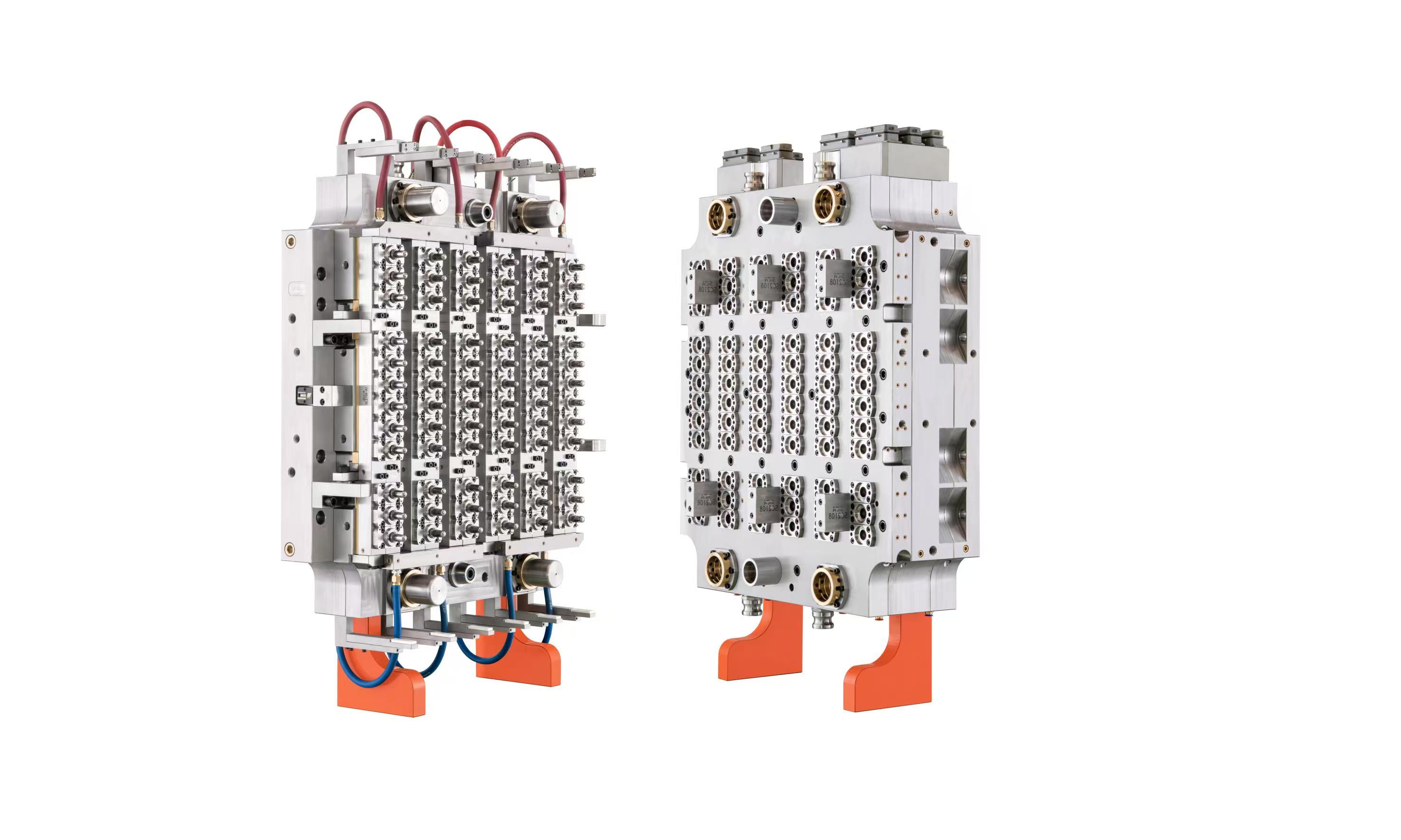
A: Preform molds are highly specialized tools designed for two-stage processes, like PET blow molding. They require exceptional thermal management to cool thick-walled preforms rapidly. Furthermore, they demand incredibly tight neck ring tolerances to ensure proper sealing during the final bottle-blowing phase.
A: Aluminum is strictly viable for low-to-medium volumes, typically under 50,000 parts. It works best with non-abrasive materials. It is the ideal choice when time-to-market is the overriding priority, as it machines much faster than steel and offers superior heat dissipation for rapid prototyping.
A: You must verify their steel origins to avoid counterfeit metals. Ask for past cycle-time reduction case studies to prove their engineering capability. Finally, clearly define the tool maintenance schedule and verify their in-house machining capabilities to avoid risks associated with outsourced production.