
Views: 0 Author: Site Editor Publish Time: 2026-08-06 Origin: Site


Misalignment in tooling terminology causes major headaches for injection molders and OEM suppliers alike. Confusion on the shop floor often leads to incorrect part orders. These errors cause delayed maintenance and extended machine downtime. In PET preform production, technicians frequently swap terms like "lip cavity," "preform lip mold," and "neck ring." People use them interchangeably during daily operations.
However, you must separate the geometric feature from the mechanical component. This distinction becomes critical during tooling procurement, retrofitting, or defect troubleshooting. Using the wrong term can result in manufacturing custom parts you cannot use. It also risks catastrophic damage to your existing tooling stack.
This article clarifies standard OEM tooling definitions. We detail how these specific components interact within the mold stack. You will also learn a strict evaluation framework for sourcing replacement parts effectively. Following these guidelines ensures seamless production and protects your tooling investments.
Understanding the exact difference between these two terms prevents costly procurement errors. It also ensures maintenance teams communicate clearly. We must separate the physical hardware from the molded geometry.
The neck ring represents the physical split mold halves. They encapsulate the upper portion of the preform during injection. This hardware performs several high-stress tasks every cycle. It forms the threads, the pilfer-proof ring, and the support ledge. The pilfer-proof ring is also known as the tamper-evident band.
Furthermore, the neck ring houses independent water cooling circuits. These circuits are absolutely essential for thermal regulation. They stabilize the thickest and most complex geometry of the preform before ejection. Without precise cooling here, the preform would warp immediately upon release.
The preform lip refers strictly to the uppermost flat surface of the plastic part. It seals directly against the final closure or cap. Achieving a flawless lip prevents future carbonation loss in beverage bottles.
Industry veterans often use the colloquial term preform lip mold on the floor. In highly technical contexts, this term may actually refer to a distinct top-stripper or sealing face insert. This varies depending on specific OEM architectures. You must verify what your team actually means.
Requesting a "lip mold" from a manufacturer without specifying the machine architecture carries high risk. Systems like Husky, SIPA, and Demark utilize completely different stack designs. A vague request can result in receiving incompatible split-ring assemblies. You might receive a top sealing insert when you actually needed the split threaded blocks.
Tooling Terminology Comparison
| Feature | Neck Ring | Preform Lip |
|---|---|---|
| Nature | Physical tooling component (Hardware) | Plastic part geometry (Product Feature) |
| Function | Forms threads, support ledge, and provides cooling | Provides a sealing surface for the final cap |
| Movement | Actuates (splits open) during ejection | Static geometric outcome on the plastic |
| Maintenance | Requires frequent lubrication and taper checks | Requires visual inspection for top-load damage |
The neck ring does not operate in isolation. It functions as an active participant in a highly pressurized environment. Its interaction determines the success of the entire molding cycle.
The neck ring acts as the critical bridge between the preform mold core and cavity. It utilizes precision-machined tapers. These tapers lock the core and cavity into absolute concentricity. This locking occurs precisely during the application of clamping tonnage. A perfect fit prevents core shift. Core shift otherwise leads to uneven wall thickness in the preform body.
The shut-off surfaces demand microscopic precision. The boundary between the neck ring and the cavity plate must withstand extreme injection pressures. A microscopic misalignment here causes immediate issues. It allows molten PET to escape, creating split-line flash on the preform threads. Flash ruins the aesthetic and functionally blocks cap application.
Unlike the fixed cavity block, neck rings must actuate. They split open via mechanical cams or robotic take-out plates. This movement releases the preform from the stack. The repetitive opening and closing subject the components to immense mechanical wear over millions of cycles.
Replacing a neck ring requires comprehensive system checks. You cannot simply install a new ring and run the machine. You must check the corresponding wear on the core and cavity tapers. Skipping this step often leads to immediate tooling damage. New, sharp tapers will gall against worn, rounded cavity plates. This ruins both components instantly.
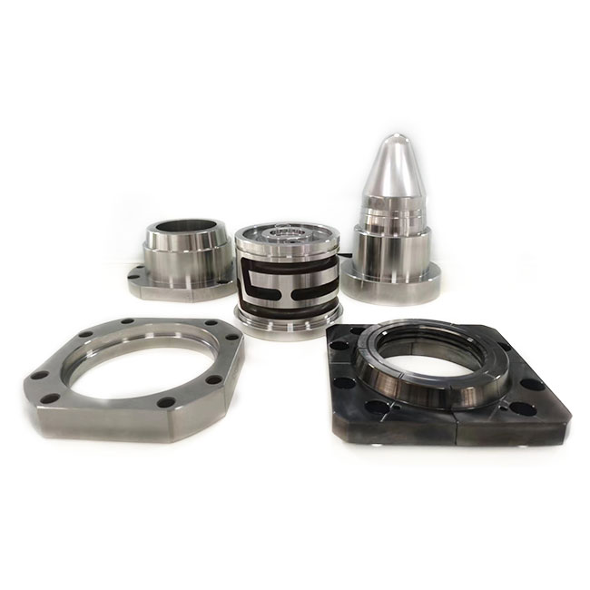
Proactive maintenance saves millions in lost production time. Operators must learn to read the plastic. Defects on the preform directly indicate specific wear patterns on the tooling.
You can trace most visual defects back to specific hardware failures. Pay close attention to these three major indicators:
Neck rings typically require refurbishment or replacement more frequently than main cavity blocks. The mechanical friction of opening and closing every single cycle accelerates wear. Core and cavity components remain static during injection, but the split rings slide. This sliding action degrades the protective coatings over time.
Procurement teams must adjust their inventory models. When inventorying preform mold accessories, treat neck rings as high-wear consumables. Do not wait for a catastrophic failure. You require a minimum of one backup set per active mold. This buffer prevents lengthy machine stoppages during unexpected maintenance events.
Tooling upgrades often aim to reduce resin consumption. However, changing the preform geometry changes the thermal dynamics. You must simulate these changes before cutting any steel.
Beverage brands constantly push for lighter packaging. When changing a neck finish, the neck ring geometry changes significantly. Moving from a standard PCO 1810 to a short-height PCO 1881 saves substantial resin. However, it alters how the plastic fills the cavity. The new geometry demands a completely different cooling approach.
Executing a PET preform moldflow analysis is non-negotiable before finalizing a neck ring redesign. It validates whether the existing cooling circuits can manage the new heat load. If the new geometry traps heat, cycle times will extend. Extended cycle times destroy the financial ROI of lightweighting projects. Simulation guarantees your cooling channels align optimally.
Moldflow simulation prevents costly trial-and-error runs on the factory floor. It identifies potential short shots before they happen. It spots air traps hiding within the complex thread profile. Furthermore, simulation highlights areas of excessive shear stress near the injection gate. This stress could easily propagate up to the neck, causing structural weakness in the final bottle.
Not all aftermarket suppliers produce equal quality. You must apply strict evaluation criteria when sourcing replacement neck rings. A cheap replacement can destroy a million-dollar mold base.
Never compromise on tooling metallurgy. You must specify premium stainless tooling steel for neck rings. Acceptable grades include Stavax or S136. The steel must be hardened to 48–52 HRC. This specific hardness range resists mechanical wear during actuation. It also prevents water corrosion inside the cooling channels.
Compare OEM offerings against aftermarket options carefully. Evaluate if the supplier uses advanced conformal cooling or standard drilled lines. Conformal cooling wraps around the thread profile, offering superior cycle times. Always verify compatibility with your existing manifold flow rates. A mismatched flow rate causes turbulent dead zones.
Interchangeability separates professional toolmakers from amateurs. Ask specific questions during the quoting phase:
Look for a clear trust indicator. Credible suppliers will always require your exact core and cavity taper drawings before quoting a replacement neck ring. If they quote blindly, walk away.
Start by auditing your current mold drawings. Verify the original OEM specifications against your physical tooling. Request a sample single-cavity stack from your new supplier. Perform rigorous tolerance testing on this single stack. You must validate the fit and cooling performance before committing to a full 48-cavity or 96-cavity tooling overhaul.
The distinction between a preform lip and a neck ring is far more than semantics. It dictates maintenance accuracy and procurement success. The preform lip remains a product feature, while the neck ring represents a highly engineered mold component. Knowing the difference streamlines communication across your entire supply chain.
Treat the neck ring, core, and cavity as an interdependent mechanical system. Upgrading or replacing one component inherently requires verifying the exact tolerances of the others. Ignoring this reality leads to rapid tooling degradation and unacceptable defect rates.
Consult with a specialized PET mold tooling engineer today. Audit your current neck ring wear immediately. Establish a data-backed replacement schedule to maximize machine uptime and preserve product quality.
A: Yes, provided the aftermarket supplier guarantees exact taper angles, shut-off dimensions, and cooling circuit alignment. However, mixing components without verifying stack-up tolerances voids warrantees and risks tooling damage.
A: Leaks typically stem from degraded O-rings or corrosion inside the water channels due to poor water treatment. They can also result from micro-cracks in the steel caused by excessive clamping force combined with thermal shock.
A: Preventative maintenance and dimensional checks should occur every 1 to 1.5 million cycles. Operators should use a go/no-go gauge on the preform threads. Deep ultrasonic cleaning of water channels must happen at standard PM intervals.


